
Introduction
Recent advances in implant macrogeometry allow clinicians to better tailor treatment to the specific anatomical and biological needs of each patient. Full-arch rehabilitation planning presents inherent challenges, requiring careful consideration of the multiple implant-supported solutions available. Each option must be critically evaluated in terms of its clinical advantages and limitations. Optimal outcomes are achieved by integrating evidence-based protocols with the patient’s individual anatomical conditions, functional demands, and the clinician’s surgical and prosthetic approach.
Within each treatment modality, implant macrogeometry plays a pivotal role in achieving primary stability and ensuring favorable bone-implant interactions. It is often necessary to select different implant designs based on bone density, volume, and cortical engagement.
Equally important are the implant material and connection technologies that contribute to long-term success. The Roxolid® alloy offers superior strength and fatigue resistance compared to titanium, allowing for reduced implant diameters without compromising mechanical stability. The SLActive® surface enhances osseointegration by promoting faster and more predictable bone healing through its hydrophilic properties. Additionally, the TorcFit™ internal connection provides a robust and stable implant-abutment interface, minimizing micro-movements and bacterial infiltration, which are critical factors in preserving peri-implant bone.
The Straumann iEXCEL™ implant family, with the introduction of the new BLC — a tapered internal connection implant — expands upon the existing BLX portfolio. Ranging from the aggressive thread design of the X series to the more conservative, conical apical geometry of the BLC, the system now offers versatility across a spectrum of bone types and clinical scenarios.
The present case illustrates the clinical rationale and decision-making process involved in the management of an atrophic edentulous maxilla, highlighting the role of macrogeometry and advanced implant technologies in enhancing primary stability and long-term predictability.
Initial situation
A 65-year-old female patient presented to the clinic seeking rehabilitation of the edentulous maxilla. One year prior, she had undergone an immediate loading procedure in the mandible, restored with a metal-acrylic implant-supported fixed prosthesis. Having successfully completed the lower arch treatment, she was now ready to proceed with the maxillary rehabilitation.
Clinical examination revealed an atrophic, fully edentulous maxilla, a finding corroborated by imaging studies.
No significant medical findings, no smoking or other toxic habits, and no current medications or allergies were reported. We classify this patient as ASA 1.
Figs. 1-4 Initial clinical and radiological assessment of the edentulous maxilla before treatment.
Treatment planning
To enhance preoperative assessment and facilitate surgical planning, 3D-printed bone models were fabricated based on the patient’s CBCT data.
Following a thorough discussion with the patient regarding the advantages and limitations of various treatment options — including zygomatic implants, subperiosteal solutions, and sinus augmentation — a treatment plan was agreed upon. The chosen approach involved bilateral maxillary sinus elevation using a xenograft in combination with a resorbable membrane.
After a healing period of nine months, standard implant placement was performed. Three months later, a stage-two procedure was carried out to expose the implants and connect the abutments, followed by the delivery of a fixed provisional prosthesis. Final impressions were then taken for the fabrication of a definitive metal-acrylic implant-supported restoration.
Figs. 5,6 3D-printed bone models produced using Rapid Shape technology, utilized for detailed case evaluation and surgical planning.
Surgical procedure
Sinus lift procedure
The treatment was planned in two main surgical stages: initial bilateral sinus elevation, followed nine months later by implant placement and, subsequently, a stage-two procedure for abutment connection.
The sinus augmentation was performed in two separate surgical appointments, spaced one month apart — first on the left side, then on the right.
Preoperatively, the patient received 500 mg of azithromycin one hour prior to surgery. Local anesthesia was administered using articaine with 1:100,000 epinephrine buccally and 1:200,000 epinephrine palatally.
The sinus elevation technique involved a crestal incision followed by a full-thickness mucoperiosteal flap. A modified Caldwell-Luc approach was used to prepare a lateral bony window. The Schneiderian membrane was carefully elevated to the medial wall to ensure adequate vascularization from the sinus walls. A resorbable collagen membrane was first placed under the Schneiderian membrane to protect it, and the sinus cavity was grafted with large granules of inorganic hydroxyapatite (Straumann® Xenograft).
The lateral bony window was repositioned over the grafted area, and a second resorbable membrane (Straumann® Membrane Flex 15 x 20 mm) was placed to cover the entire site. The membrane was stabilized using horizontal periosteal mattress sutures. The flap was closed with simple interrupted sutures.
Postoperative medication included azithromycin, paracetamol, etoricoxib, an antihistamine, and saline nasal irrigation.
Figs. 7-14 Sequence of the left maxillary sinus elevation procedure (from left to right): Full-thickness mucoperiosteal flap elevation; delimitation of the lateral window using piezoelectric surgery; removal and preservation of the lateral bony wall; elevation of the Schneiderian membrane; exposure of the medial wall for vascular support; placement of xenograft material in the sinus cavity; coverage with a resorbable collagen membrane; final wound closure with sutures.
Figs. 15-22 Right maxillary sinus elevation: Full-thickness flap elevation, lateral window preparation with piezosurgery, Schneiderian membrane elevation, xenograft placement, membrane coverage, and suturing.

Fig. 23

Fig. 24
Figs. 23,24 Radiographic evaluation following bilateral sinus elevation, confirming graft placement and membrane integrity.
Implant placement
Nine months following the sinus augmentation procedures, a CBCT scan was obtained to evaluate graft integration and bone regeneration. The scan was matched with the patient’s full upper denture using coDiagnostiX® software to guide implant planning. Healing was uneventful.
The treatment plan included placement of:
- Two BLX Ø4.0 x 12 mm implants in the maxillary tuberosities,
- Two BLX Ø4.0 x 12 mm implants in the grafted sinus areas (left and right),
- Two BLC Ø3.5 x 12 mm implants positioned in the region of the anterior sinus wall.
All implants featured Straumann’s SLActive® surface and TorcFit™ internal connection. Implant bed preparation was performed following the manufacturer’s recommended drilling protocol. The sequence included an initial Ø2.2 mm VeloDrill®, followed by a Ø2.8 mm drill, and then direct implant placement. For the Ø4.0 mm diameter implants, a final Ø3.5 mm drill was additionally used to accommodate the wider body.
This is where implant macrogeometry makes a real difference. In softer bone or areas with sufficient width, a more aggressive thread design is preferred—“aggressive” in the sense that the osteotomy is slightly undersized, allowing the implant’s cutting flutes to engage and create primary stability.
In the tuberosity, only the spear drill and a 2.2 mm drill to a depth of 2 mm were used, allowing the implant itself to complete the preparation. This technique requires excellent tactile sensitivity and hand control to prevent the implant from deviating into unrestorable positions.
Conversely, in the area between the nasal plate and the anterior wall of the sinus, a less aggressive thread design is essential to avoid fractures in these delicate anatomical sites. Here, the BLC technology proves valuable, enabling the implant to seat securely without excessive engagement of the lateral wall threads. Instead, it relies on a wedge effect created by a conical implant body and apical thread design.
All implants achieved primary stability at the time of placement. However, due to the low bone density, a submerged healing (with cover screws) protocol was followed, allowing three months for osseointegration.
At the three-month follow-up, a second-stage surgery was performed, and prosthetic abutments were placed as follows:
- The two BLX implants in the tuberosities received SRA Ø3.5 mm angled abutments (30°),
- The BLX implants in the grafted sinus received SRA Ø2.5 mm angled abutments (17°),
- The BLC implants in the anterior sinus wall received SRA Ø2.5 mm angled abutments (30°).
At this stage, the full denture was converted into an implant-retained fixed provisional prosthesis using temporary SRA cylinders. Occlusion was carefully adjusted, and the screw access channels were sealed with Teflon tape and provisional composite resin.
Figs. 25-30 From left to right: Implant planning in coDiagnostiX® software, CBCT confirmation of sinus graft healing, matching the prosthesis in the software for implant and SRA abutment planning, frontal view of prosthesis alignment, frontal view of implant placement planning, and frontal view with virtual SRA abutments in place.
Figs. 31,32 Panoramic radiograph showing the final position of the implants: Two BLX implants placed in the maxillary tuberosities, two BLX implants in the grafted sinus areas (left and right), and two BLC implants in the anterior maxilla adjacent to the sinus wall.
Figs. 33-35 From left to right: Sagittal view in coDiagnostiX® showing planned placement of a Straumann® BLX Ø4.0 x 12 mm implant in the maxillary sinus, corresponding sagittal CBCT slice confirming anatomical positioning, and detailed view of the BLX implant macrogeometry (Straumann®, SLActive® surface, TorcFit™ connection).
Figs. 36-38 From left to right: Sagittal view in coDiagnostiX® showing planned placement of a Straumann® BLC Ø3.5 x 12 mm implant in the anterior maxilla, corresponding sagittal CBCT slice confirming bone availability and positioning, and detailed view of the BLC implant macrogeometry (Straumann®, SLActive® surface, TorcFit™ connection).

Fig. 39
Fig. 39 Implant placement in the tuberosity and sinus regions. In these areas, a more aggressive thread design enhances primary stability. Note that, in the tuberosity, the implant itself serves as the drilling tool—only the spear drill is used. In the sinus region, follow the recommended drilling protocol for Type 1/2 bone to ensure optimal implant bed preparation.
Figs. 40,41 From left to right: Sagittal view in coDiagnostiX® showing planned placement of a Straumann® BLX Ø4.0 x 12 mm implant in the maxillary tuberosity, corresponding sagittal CBCT slice confirming anatomical positioning.
Figs. 42,43 Note the importance of a less aggressive thread design in proximity to the anterior wall of the maxillary sinus and the lateral nasal plate. This design helps minimize the risk of perforation and enhances implant stability in anatomically delicate areas.

Fig. 44
Fig. 44 Three months after implant placement: second-stage surgery with soft tissue exposure and placement of healing abutments (caps) on all implants.
Prosthetic procedure
Three months after the delivery of the provisional restoration and confirmation of implant integration, final impressions were taken using a high-precision polyvinyl siloxane (PVS) material. Two definitive master casts were obtained and mounted on a semi-adjustable articulator to reproduce the patient’s occlusal dynamics.
This is where the Straumann iEXCEL™ family shows its versatility: regardless of whether you choose the BLC or BLX implant macrogeometry, the prosthetic components remain the same across the entire system.
A verification index was used to confirm a passive fit of the prosthetic framework. A wax tooth try-in was then performed to evaluate esthetics, phonetics, and occlusion prior to finalization.
The definitive prosthetic rehabilitation consisted of a maxillary and mandibular implant-supported metal-acrylic hybrid prosthesis, fabricated over a CAD/CAM-milled titanium bar to ensure rigidity and long-term stability.

Fig. 45
Fig. 45 Clinical view of the healed mucosa three months post-implant placement, showing the Straumann® SRA abutments in place: 30° angled abutments in the tuberosity and anterior regions, and 17° angled abutments in the grafted sinus areas.
Figs. 46,47 Frontal and occlusal views of the provisional prosthesis, relined with acrylic at the stage-two procedure and adapted for immediate connection to the SRA abutments.

Fig. 48
Fig. 48 Panoramic radiograph showing the provisional restoration in function following stage-two surgery.

Fig. 49
Fig. 49 Passive fit verification of the laboratory-fabricated acrylic verification bar.
Figs. 50-52 Wax try-in of the prosthesis, allowing verification of esthetics, occlusion, and functional parameters prior to finalization.
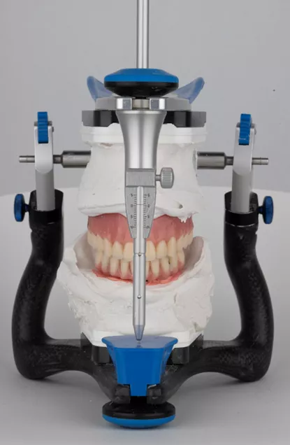
Fig. 53
Fig. 53 Mounting of master casts on a semi-adjustable articulator for occlusal analysis and prosthetic planning.
Figs. 54-56 Occlusal view of the final implant-supported prosthesis and frontal view of the completed laboratory-fabricated restoration.
Figs. 57-59 Final prosthesis in occlusion demonstrating functional and esthetic integration. Occlusal view of the final implant-supported metal-ceramic restoration.
Figs. 60-62 Final panoramic radiograph showing the implant rehabilitation: BLX implants in the maxillary tuberosities and grafted sinus, BLC implants in the anterior maxilla, and TLX NT implants supporting the mandibular restoration. Note also the horizontal CBCT views demonstrating good integration and adequate anteroposterior (AP) spread of the implants.
Treatment outcomes
The approach to full-mouth rehabilitation of an atrophic maxilla is among the most demanding in implant dentistry, requiring a delicate balance between detailed treatment planning, the surgical expertise of the clinician, careful selection of biomaterials, and implant macrogeometry. Equally critical is the precise control of anteroposterior (AP) spread, interocclusal space, cantilever length, occlusion, and esthetic parameters such as smile line, gingival symmetry, tooth proportions, and facial harmony.
In this case, each step was executed uneventfully, and the meticulous coordination of all these factors led to a highly stable and esthetically pleasing full-mouth rehabilitation. The patient is now ready to begin the maintenance protocols—not only at the peri-implant level, but also through annual prosthodontic follow-ups to monitor occlusion, prosthetic components, and long-term esthetic integration.
Figs. 63-65 Final patient smile demonstrating esthetic and functional rehabilitation outcomes.
Author’s testimonial
“To me, this case represents true freedom — the freedom to select the ideal implant macrogeometry tailored precisely to each individual site. It embodies the ability to leverage the full versatility of the iEXCEL family in a complex scenario where every detail counts. Utilizing state-of-the-art implant materials and connection technologies empowers me to push the boundaries of what is achievable, ensuring optimal outcomes and long-term success for my patients.”